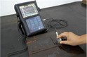

Ultrasonic flaw detection is a crucial technique in the field of non-destructive testing, enabling the detection of internal defects in materials without causing any damage. Among the various ultrasonic testing methods, the Time-of-Flight Diffraction (TOFD) method has gained significant popularity due to its high sensitivity, accuracy, and ability to provide detailed information about flaws. As a leading Ultrasonic Flaw Detection supplier, we are well-versed in the principles and applications of the TOFD method. In this blog post, we will delve into how the TOFD method works in ultrasonic flaw detection.
Principles of Ultrasonic Waves
Before we explore the TOFD method, it's essential to understand the basic principles of ultrasonic waves. Ultrasonic waves are sound waves with frequencies higher than the upper audible limit of human hearing, typically above 20 kHz. In ultrasonic flaw detection, these waves are generated by a transducer, which converts electrical energy into mechanical vibrations. When the ultrasonic waves are introduced into a material, they travel through it until they encounter a discontinuity, such as a crack, void, or inclusion. At the discontinuity, a portion of the ultrasonic waves is reflected back to the transducer, while the rest continues to propagate through the material.
The TOFD Method: An Overview
The Time-of-Flight Diffraction (TOFD) method is based on the principle of diffraction of ultrasonic waves at the tips of a flaw. Unlike conventional ultrasonic testing methods that rely on the reflection of ultrasonic waves from the flaw, the TOFD method measures the time taken for the ultrasonic waves to diffract around the tips of the flaw. This time measurement provides information about the size, location, and orientation of the flaw.
The TOFD method uses two transducers: a transmitter and a receiver. The transmitter emits an ultrasonic beam into the material, which travels through it until it encounters a flaw. At the tips of the flaw, the ultrasonic waves are diffracted, and the diffracted waves are detected by the receiver. The time taken for the ultrasonic waves to travel from the transmitter to the flaw tip and then to the receiver is measured, and this time measurement is used to calculate the position of the flaw tip.
How the TOFD Method Works
Setup
The first step in the TOFD method is to set up the testing equipment. The two transducers are placed on opposite sides of the test piece, with the ultrasonic beam directed towards the area of interest. The transducers are usually coupled to the test piece using a couplant, such as water or a gel, to ensure efficient transmission of the ultrasonic waves.
Ultrasonic Wave Propagation
Once the equipment is set up, the transmitter emits an ultrasonic beam into the material. The ultrasonic beam travels through the material until it encounters a flaw. At the flaw, a portion of the ultrasonic waves is diffracted around the tips of the flaw, while the rest continues to propagate through the material.
Detection of Diffracted Waves
The diffracted waves are detected by the receiver, which converts the mechanical vibrations into electrical signals. These electrical signals are then amplified and processed by the TOFD instrument.
Time Measurement
The TOFD instrument measures the time taken for the ultrasonic waves to travel from the transmitter to the flaw tip and then to the receiver. This time measurement is known as the time-of-flight (TOF). The TOF is directly related to the distance between the flaw tip and the transducers, and it can be used to calculate the position of the flaw tip.
Data Analysis
The TOF measurements obtained from the TOFD instrument are used to create a TOFD image, which shows the position and size of the flaw. The TOFD image is a graphical representation of the time-of-flight data, with the horizontal axis representing the position along the test piece and the vertical axis representing the depth of the flaw. The TOFD image provides detailed information about the flaw, including its length, height, and orientation.


Advantages of the TOFD Method
The TOFD method offers several advantages over conventional ultrasonic testing methods, including:
- High Sensitivity: The TOFD method is highly sensitive to small flaws, making it suitable for the detection of critical defects in materials.
- Accurate Flaw Sizing: The TOFD method provides accurate information about the size and position of the flaw, enabling precise assessment of the defect.
- Full Volume Coverage: The TOFD method can provide full volume coverage of the test piece, ensuring that all potential flaws are detected.
- Rapid Inspection: The TOFD method is a rapid inspection technique, allowing for quick and efficient testing of large areas.
- Non-Destructive: The TOFD method is a non-destructive testing technique, which means that the test piece can be reused after testing.
Applications of the TOFD Method
The TOFD method is widely used in various industries, including aerospace, automotive, power generation, and oil and gas. Some of the common applications of the TOFD method include:
- Weld Inspection: The TOFD method is commonly used for the inspection of welds in pipelines, pressure vessels, and other structures. It can detect flaws such as lack of fusion, porosity, and cracks in the weld.
- Castings and Forgings Inspection: The TOFD method can be used to inspect castings and forgings for internal defects, such as shrinkage cavities, porosity, and inclusions.
- Corrosion Detection: The TOFD method can be used to detect corrosion in pipes and other structures. It can provide information about the depth and extent of the corrosion, which is useful for assessing the remaining life of the structure.
- Composite Materials Inspection: The TOFD method can be used to inspect composite materials for delamination, voids, and other defects. It is particularly useful for the inspection of aerospace components, where the integrity of the composite materials is critical.
Comparison with Other Non-Destructive Testing Methods
While the TOFD method offers several advantages, it is not suitable for all applications. Other non-destructive testing methods, such as Dye Penetrant Inspection and X Ray Inspection, may be more appropriate in certain situations.
- Dye Penetrant Inspection: Dye penetrant inspection is a simple and cost-effective method for detecting surface-breaking defects. It is commonly used for the inspection of small components and parts. However, it is not suitable for detecting internal defects.
- X Ray Inspection: X ray inspection is a powerful non-destructive testing method that can provide detailed information about the internal structure of a material. It is commonly used for the inspection of complex components and parts. However, it requires specialized equipment and trained personnel, and it can be expensive.
Conclusion
The Time-of-Flight Diffraction (TOFD) method is a powerful and reliable technique for ultrasonic flaw detection. It offers high sensitivity, accuracy, and full volume coverage, making it suitable for a wide range of applications. As a leading Ultrasonic Flaw Detection supplier, we have the expertise and experience to provide high-quality TOFD testing services. If you are interested in learning more about the TOFD method or would like to discuss your specific testing requirements, please contact us. We look forward to working with you to ensure the quality and safety of your products.
References
- Krautkramer, J., & Krautkramer, H. (1990). Ultrasonic Testing of Materials. Springer-Verlag.
- American Society for Nondestructive Testing (ASNT). (2008). Ultrasonic Testing Handbook. ASNT.
- British Standards Institution (BSI). (2013). BS EN ISO 16828:2013 Non-destructive testing - Ultrasonic testing - Time-of-flight diffraction technique as a method for detection and sizing of discontinuities. BSI.