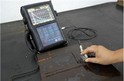

Calibrating ultrasonic flaw detection equipment is a critical process that ensures the accuracy and reliability of the inspection results. As a leading supplier of Ultrasonic Flaw Detection equipment, I understand the importance of proper calibration in the field of non - destructive testing (NDT). In this blog, I will share a comprehensive guide on how to calibrate ultrasonic flaw detection equipment, which will be useful for both novice and experienced NDT technicians.
Understanding the Basics of Ultrasonic Flaw Detection
Before delving into the calibration process, it's essential to have a basic understanding of how ultrasonic flaw detection works. Ultrasonic flaw detection is a non - destructive testing method that uses high - frequency sound waves to detect internal flaws in materials. The equipment consists of a transducer that emits ultrasonic waves into the test piece. When these waves encounter a flaw, such as a crack or a void, a portion of the wave is reflected back to the transducer, which then converts the reflected signal into an electrical signal that can be analyzed on the display of the flaw detector.
Pre - calibration Preparations
- Equipment Inspection: Before starting the calibration, thoroughly inspect the ultrasonic flaw detection equipment. Check the transducer for any visible damage, such as cracks or worn - out elements. Ensure that the cables are in good condition, without any signs of fraying or loose connections. A damaged transducer or cable can significantly affect the accuracy of the calibration and the subsequent inspection results.
- Selection of Calibration Blocks: Calibration blocks are essential tools for calibrating ultrasonic flaw detection equipment. They are made of materials with known acoustic properties and contain artificial flaws of specific sizes and shapes. The most commonly used calibration blocks are the IIW (International Institute of Welding) blocks. Select the appropriate calibration block based on the type of inspection and the range of flaw sizes you need to detect.
- Cleaning: Clean the surface of the calibration block and the transducer. Any dirt, oil, or debris on the surface can interfere with the transmission of ultrasonic waves, leading to inaccurate calibration results. Use a suitable cleaning agent and a soft cloth to clean the surfaces.
Calibration Steps
1. Zero - point Calibration
The zero - point calibration is used to set the starting point of the time - base on the flaw detector display.
- Place the transducer on the calibration block at a known distance from a reference reflector, such as a flat - bottomed hole or a side - drilled hole.
- Adjust the time - base controls on the flaw detector until the first echo from the reference reflector appears at the correct position on the display. This position corresponds to the time it takes for the ultrasonic wave to travel to the reflector and back to the transducer.
- Fine - tune the zero - point setting to ensure that the position of the echo is accurate. This step is crucial as it provides the foundation for accurate distance measurements during the inspection.
2. Sensitivity Calibration
Sensitivity calibration determines the ability of the ultrasonic flaw detection equipment to detect flaws of a specific size.
- Select a reference reflector of a known size on the calibration block. For example, a side - drilled hole of a particular diameter.
- Adjust the gain control on the flaw detector until the echo from the reference reflector reaches a specific height on the display. This height is usually set as a percentage of the full - screen height, such as 80%.
- Once the desired echo height is achieved, the sensitivity of the equipment is set. This setting ensures that the equipment can detect flaws of a similar size during the actual inspection.
3. Distance - Amplitude Correction (DAC)
The amplitude of the ultrasonic echo decreases as the distance between the transducer and the flaw increases. Distance - Amplitude Correction (DAC) is used to compensate for this decrease in amplitude.


- Use a calibration block with multiple reference reflectors at different distances. Measure the echo amplitudes from these reflectors and plot them on a graph.
- Adjust the DAC curve on the flaw detector to match the measured amplitudes. The DAC curve allows the operator to accurately evaluate the size of flaws at different depths in the test piece.
4. Angle Calibration (for Angle - Beam Transducers)
If you are using an angle - beam transducer, angle calibration is necessary to ensure the correct angle of the ultrasonic beam.
- Place the angle - beam transducer on a calibration block with a known angle reflector.
- Adjust the angle - setting controls on the flaw detector until the echo from the angle reflector appears at the correct position on the display.
- Check the accuracy of the angle calibration by measuring the angle of the beam using a suitable measuring device.
Verification of Calibration
After completing the calibration process, it is essential to verify the accuracy of the calibration.
- Repeatability Test: Perform multiple measurements on the calibration block using the calibrated equipment. The results should be consistent within an acceptable range. If there are significant variations in the measurements, re - check the calibration settings and make any necessary adjustments.
- Comparison with Known Standards: Compare the calibration results with established industry standards or reference values. This helps to ensure that the equipment is calibrated correctly and meets the required accuracy criteria.
Troubleshooting during Calibration
During the calibration process, you may encounter some problems. Here are some common issues and their solutions:
- Inconsistent Echoes: If the echoes on the display are inconsistent, check the coupling between the transducer and the calibration block. Ensure that there is a good acoustic coupling by using an appropriate coupling agent, such as a gel or a liquid. Also, check for any air bubbles between the transducer and the block.
- Incorrect Echo Height: If the echo height is not reaching the desired level, check the gain settings and the sensitivity of the equipment. It could also be due to a damaged transducer or a problem with the calibration block.
- Erratic Time - base: An erratic time - base can be caused by a loose cable connection or a problem with the internal electronics of the flaw detector. Check the cables and, if necessary, contact the manufacturer for further troubleshooting.
Importance of Regular Calibration
Regular calibration of ultrasonic flaw detection equipment is crucial for maintaining its accuracy and reliability. Over time, the performance of the equipment can degrade due to factors such as normal wear and tear, temperature changes, and electrical interference. By calibrating the equipment at regular intervals, you can ensure that it continues to provide accurate and consistent inspection results.
Other Non - destructive Testing Methods
In addition to Ultrasonic Flaw Detection, there are other non - destructive testing methods available, such as Dye Penetrant Inspection and Magnetic Powder Inspection. Each method has its own advantages and limitations, and in some cases, multiple methods may be used in combination to obtain more comprehensive inspection results.
Conclusion
Calibrating ultrasonic flaw detection equipment is a complex but essential process that requires careful attention to detail. By following the steps outlined in this blog, you can ensure that your equipment is calibrated accurately and provides reliable inspection results. As a supplier of ultrasonic flaw detection equipment, we are committed to providing high - quality products and technical support to our customers. If you are interested in purchasing our ultrasonic flaw detection equipment or have any questions about calibration or non - destructive testing, please feel free to contact us for further discussion and procurement negotiations.
References
- ASNT (American Society for Nondestructive Testing). "Ultrasonic Testing Handbook".
- ISO (International Organization for Standardization) standards related to ultrasonic testing and calibration.
- IIW (International Institute of Welding) publications on non - destructive testing and calibration blocks.